
Please note: This article is provided for existing installations only. Gimmal Physical no longer supports RFID for new customers.
Installation Settings
Gimmal Physical RFIDConnect is a Windows system tray application that allows users to interact with RFID-tagged items to perform check-in/check-out operations.
Setting Up Gimmal Physical RFIDConnect
To get started with RFIDConnect, you need:
-
RFID Reader Hostname/IP Address
-
Gimmal Physical WebServices URL
Initial Set Up
Set the WebService URL:
-
Navigate to the RFIDConnect installation directory.
-
Open Gimmal PhysicalRFIDConnect.exe.config in a text editor.
-
Find the setting tag where the name attribute equals “WebserviceURL”. EX:
<setting name="WebserviceURL" serializeAs="String"><value></value>
</setting>
-
Set the Value tag to the Gimmal Physical WebService URL.
-
Save the file.
Set and configure the RFID Reader and Antenna:
-
Start the application.
-
Right click on the RFIDConnect Icon in the system tray.
-
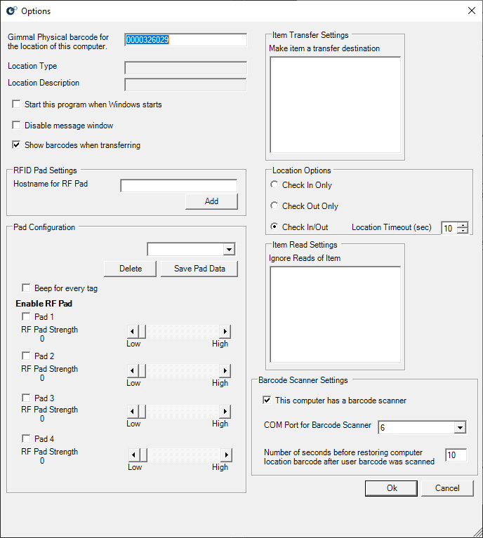
Click on Options
-
Enter the Hostname/IP Address in the ‘Hostname for RF Pad‘ text box in the RFID Pad Settings section.
-
Click Add.
-
Select the RFID Pad from the dropdown menu in the Pad Configuration section.
-
Check the appropriate boxes for each antenna attached to the reader and set the desired strength.
-
Click Ok
Configure Check-In/Out Operations:
RFIDConnect supports three Check In/Out modes.
Check-In Only
Check-in items by passing the tagged items over the antenna. The tagged item will be checked into the barcode to which the reader is set.
Check-Out Only
First, check out items by passing the tag for the check-out destination. Then pass the tagged item over the antenna.
Check-In/Out
-
This mode supports both check-in and check-out, with a timeout setting for the transfer destination read.
-
Example: The reader detects a transfer destination, and for the next 10 seconds any items it reads will be checked out to that destination. After 10 seconds it reverts to check-in mode.
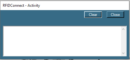
When detected, read tags will be shown in the Show Activity window. This window will open automatically unless disabled in the Options menu.
Using RFIDConnect for check-in/out requires users to define the following settings:
-
Set the Location that the RFID Reader represents: (Ex. File room, Warehouse)
-
Start the RFIDConnect application.
-
Right click on the RFIDConnect Icon in the system tray, and click on Options.
-
Enter the Gimmal Physical barcode for the item that the reader represents in the ‘Gimmal Physical barcode for the location of this computer’ textbox.
-
Click Ok.
-
-
Set which Tabs that the Reader will recognize as transfer destinations:
-
Start the RFIDConnect application.
-
Right click on the RFIDConnect Icon in the system tray, click on Options
-
Under Item Transfer Settings check the boxes for the tabs that should be recognized as a transfer destination.
-
Click Ok.
-
-
Set which Tabs to ignore reads:
-
Start the RFIDConnect application.
-
Right click on the RFIDConnect Icon in the system tray, click on Options
-
Under Ignore Reads of Item, check the boxes for the tabs that should be ignored if read.
-
Click Ok.
-

Additional Options
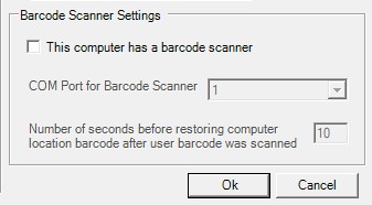
Barcode Scanner - If using RFIDConnect at a workstation that also has a Tethered Scanner, you can use the Tethered Scanner to read destination barcodes.
-
Start the RFIDConnect application.
-
Right click on the RFIDConnect Icon in the system tray, and click on Options.
-
Check the ‘This computer has a barcode scanner’ checkbox.
-
Select the COM port that the tethered scanner is using from the ‘COM Port for Barcode Scanner’ drop-down.
-
Click Ok
Programing Tags
RFIDConnect can also reprogram RFID tags:
-
Start the RFIDConnect application.
-
Right click on the RFIDConnect Icon in the system tray.
-
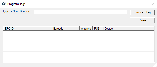
Click on Program Tags.
-
Scan the tag to reprogram.
-
Type in the new barcode.
-
Click Program Tag.
Supported Hardware
RFIDConnect supports the Zebra FX7500 RFID Reader.
|
Physical Characteristics |
|
|
Dimensions |
7.7 in. L x 5.9 in. W x 1.7 in. D
|
|
Weight |
1.9 lbs ± 0.1 lbs (0.86 kg ± 0.05 kg) |
|
Housing Material |
Die-cast aluminum, sheet metal, and plastic |
|
Visual Status Indicators |
Multicolor LEDs: Power, Activity, Status and Applications |
|
Mounting |
Keyhole and standard VESA (75mm x 75mm) |
|
Environmental |
|
|
Operating Temp. |
-4° to +131° F/-20° to +55° C |
|
Storage Temp. |
-40° to +158° F/-40° to +70° C |
|
Humidity |
5-95% non-condensing |
|
Shock/Vibration |
MIL- STD-810G |
|
Regulatory Compliance |
|
|
Safety |
UL 60950-01, UL 2043, IEC 60950-1, EN 60950-1 |
|
RF/EMI/EMC |
FCC Part 15, RSS 210, EN 302 208, ICES-003 Class B, EN 301 489-1/3 |
|
SAR/MPE |
FCC 47CFR2:OET Bulletin 65; EN 50364 |
|
Other |
ROHS, WEEE |
|
Connectivity |
|
|
Communications |
10/100 BaseT Ethernet (RJ45) w/ POE support; USB Client (USB Type B), USB Host Port (Type A) |
|
General Purpose I/O |
2 inputs, 3 outputs, optically isolated (Terminal Block) |
|
Power Supply |
POE, POE+ or +24V DC (UL Approved)
|
|
Antenna Ports |
FX 7500-2: 2 mono-static ports (Reverse Polarity TNC)
|
|
Hardware, OS, and Firmware Management |
|
|
Processor |
Texas Instruments AM3505 (600 Mhz) |
|
Memory |
Flash 512 MB; DRAM 256 MB |
|
Operating System |
Linux |
|
Firmware Upgrade |
Web-based and remote firmware upgrade capabilities |
|
Management Protocols |
RM 1.0.1 (with XML over HTTP/HTTPS and SNMP binding); RDMP |
|
Network Services |
DHCP, HTTPS, FTPS, SFPT, SSH, HTTP, FTP, SNMP and NTP |
|
Network Stack |
IPv4 and IPv6 |
|
Security |
Transport Layer Security Ver 1.2, FIPS-140 |
|
Air Protocols |
EPCglobal UHF Class 1 Gen2, ISO 18000-6C |
|
Frequency (UHF Band) |
Global Reader: 902 MHz – 928 MHz (Maximum, supports countries that use a part of this band), 865 MHz – 868 MHz
|
|
Transmit Power Output |
10 dBm to +31.5 dBm (POE+, 12V ~ 48V External DC, Universal 24V DC Power Supply); +10 dBm to +30.0 dBm (POE) |
|
Max. Receive Sensitivity |
-82 dBm |
|
IP Addressing |
Static and Dynamic |
|
Host Interface Protocol |
LLRP |
|
API Support |
Host Applications – .NET, C, and Java EMDK;
|
|
Warranty |
The FX7500-2 and FX7500-4 are warrantied against defects in workmanship and materials for one year (12 months) from the date of shipment, provided the product remains unmodified and is operated under normal and proper conditions. |